Over the fall 2025 semester I’ve worked on Taurus III, the Longhorn Rocketry Association’s newest hybrid engine. My propulsion engineering role included being the responsible engineer for the nozzle/combustion and injector subsystems.
Nozzle
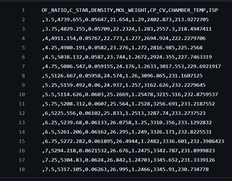
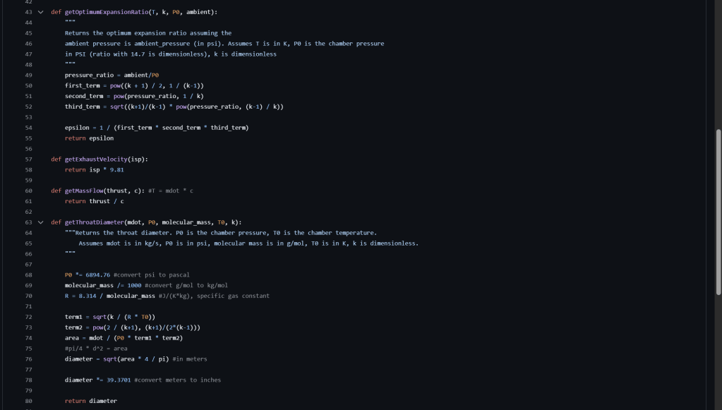
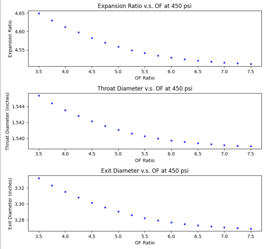
I was tasked with designing a bell nozzle assembly for our engine. I began by working out the calculations for the nozzle’s geometry. For a particular choice of O/F ratio and chamber pressure, isentropic theory dictates an optimal throat and expansion diameter. I created a python codebase to abstract these calculations and connect via Pandas to the combustion data we had collected from our parametric sweep.
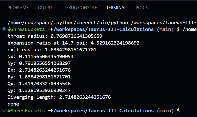
Next, I worked on generating bell nozzle contours. Using the Rao approximation, I integrated an existing codebase with our combustion data to calculate the coefficients for a canted parabola’s parametric equation (as per the Bezier method). Additionally, I chose a conical design for the converging section.
Next, I designed the actual nozzle assembly, including the insert and the flange. Isomolded graphite was chosen for the insert material while Alloy 6061 T6 was chosen for the flange.
The choice of eight 1/4″ fasteners with fine threads was validated by ensuring a safety factor greater than two for each of the following loads on the casing and fasteners:
- Fastener shear
- Casing shear (bolt tear-out)
- Casing tensile failure
- Hole bearing stress
A tangent on failure mode considerations
The fasteners were chosen to ensure that the first failure mode is the shearing of the nozzle assembly out of the engine. This failure mode ensures that the rest of the engine remains intact with performance being sacrificed. However, the failure point is around 1000 psi while the manifold pressure is regulated to 665 psi. Thus, the true first failure mode is combustion back flow which is undesirable and RUD prone. As such, our team is currently working on adding redundant systems in the manifold such as PRV and burst discs.
Next, I validated the static structural safety of the nozzle using ANSYS Mechanical. To make the model conservative, I applied frictionless supports on the case-interfacing surfaces and on the top half of the radial bolt holes. Additionally, I applied the 450 psi chamber pressure load across the converging section and the throat.
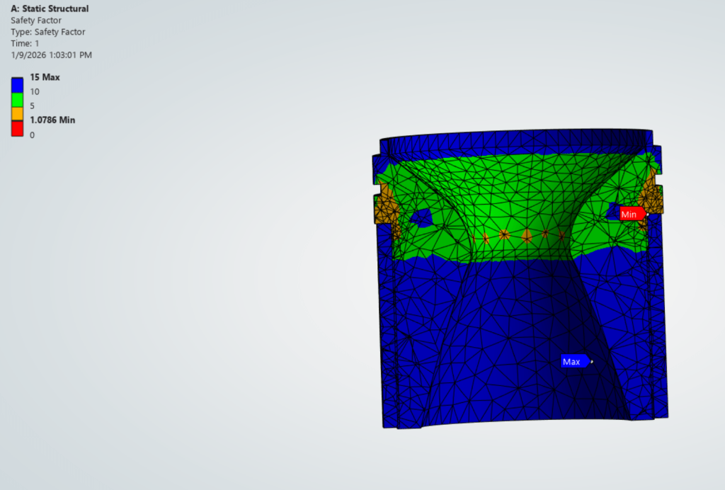
As expected, the model predicted that the stress concentration factors at the flange interface were large enough to cause failure. As such, I’m currently working on finding a proper chamfer length and angle to lessen the effects of stress concentrations before we move on to manufacturing.
